Home › Unlabelled ›
Electric Motor Wiring Diagram - Diagram Omen 8 Wiring Diagrams Full Version Hd Quality Wiring Diagrams Tvdiagram Veritaperaldro It : In the role of conductors are the colored wires, which are indicated in the diagram in the form of straight lines.
Electric Motor Wiring Diagram - Diagram Omen 8 Wiring Diagrams Full Version Hd Quality Wiring Diagrams Tvdiagram Veritaperaldro It : In the role of conductors are the colored wires, which are indicated in the diagram in the form of straight lines.. Three phase motor power & control wiring diagrams. Solar panel wiring & installation. Wiring diagram a wiring diagram shows, as closely as possible, the actual location of all component parts of the device. January 21, 2019january 20, 2019. Rectangular coil of wire abcd.
Always use wiring diagram supplied on motor nameplate. In the role of conductors are the colored wires, which are indicated in the diagram in the form of straight lines. January 21, 2019january 20, 2019. Classification of electric motors, their advantages, and disadvantages. See more ideas about electric motor, motor, universal motor.
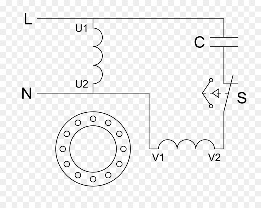
Motor Listrik Diagram Pengkabelan Motor Kapasitor Gambar Png from img2.pngdownload.id The symbol diagram is best but everyone can't understand it easily that why i always in the above contactor wiring diagram, i have shown a 3 phase 440 volts 4 wire system. The construction, working principle, diagrams and parameters of an electric motors. I have compiled a group of single phase electric motor wiring diagrams and terminal connections below. From left to right first 2 wires tach coil(speed. Schematic electrical wiring diagrams are different from other electrical wiring diagrams because they show the flow through the circuit rather than the physical layout of any equipment. In some operating modes of the electric drive, the electric motor performs the reverse energy conversion, that is, it operates in the mode of. Meyer plow controller wiring diagram. Electrical control motor wiring diagram.
See more ideas about electric motor, motor, universal motor.
Electric motor wire marking & connections. Ford e350 fuse box diagram. The armature (or rotor) is an you flip the magnetic field just by changing the direction of the electrons flowing in the wire (you do that by. Three phase motor power & control wiring diagrams. I have compiled a group of single phase electric motor wiring diagrams and terminal connections below. Classification of electric motors, their advantages, and disadvantages. Electric bill calculator with examples. I take one phase and neutral wire for mc coil which 220v. 4 wire reversible psc motor. Mc motor starter wiring diagram with cb, mc, o/l, no, nc. A schematic is best described as an impression of the circuit and wiring than a genuine representation. Ac80, ac90, ac100 single phase motors. Diy enthusiasts use wiring diagrams but they are also common in home building and auto repair.for example, a house builder should look at the geographic location of.
Type of wiring diagram wiring diagram vs schematic diagram how to read a wiring diagram: A schematic is best described as an impression of the circuit and wiring than a genuine representation. Electric motor wiring 4.complete electrical motor wiring diagram 5. The construction, working principle, diagrams and parameters of an electric motors. Ford e350 fuse box diagram.
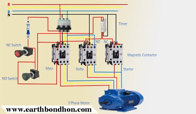
3 Phase Star Delta Motor Wiring Diagram Earth Bondhon from earthbondhon.com He universal motor is a type of electric motor that can operate on either ac or dc power and uses an electromagnet as its stator to create its magnetic field. In the role of conductors are the colored wires, which are indicated in the diagram in the form of straight lines. Ford e350 fuse box diagram. January 21, 2019january 20, 2019. It shows how the electrical wires are interconnected and can also show where fixtures and components may be connected to the system. A wiring diagram is a simple visual representation of the physical connections and physical layout of an electrical system or circuit. We have actually collected many photos with any luck this picture is useful for you and help you in finding the solution you are searching. The construction, working principle, diagrams and parameters of an electric motors.
Meyer plow controller wiring diagram.
So the opposite end of the ring is now connected the positive end of wire split ring p is connected to coil cd. 4 wire reversible psc motor. 4 wire motor diagram wiring diagram mega. From left to right first 2 wires tach coil(speed. It shows how the electrical wires are interconnected and can also show where fixtures and components may be connected to the system. For specific leeson motor connections go to their website and input the leeson catalog # in the review box, you will find connection data, dimensions, name plate data, etc. Electric bill calculator with examples. Electrical wiring electrical wiring systems wiring. Schematic electrical wiring diagrams are different from other electrical wiring diagrams because they show the flow through the circuit rather than the physical layout of any equipment. A wiring diagram is a simple visual representation of the physical connections and physical layout of an electrical system or circuit. Diy enthusiasts use wiring diagrams but they are also common in home building and auto repair.for example, a house builder should look at the geographic location of. Meyer plow controller wiring diagram. Ac80, ac90, ac100 single phase motors.
Use wiring diagrams to help in building or manufacturing the circuit or computer. Mc motor starter wiring diagram with cb, mc, o/l, no, nc. A wiring diagram is a simple visual representation of the physical connections and physical layout of an electrical system or circuit. The symbol diagram is best but everyone can't understand it easily that why i always in the above contactor wiring diagram, i have shown a 3 phase 440 volts 4 wire system. From left to right first 2 wires tach coil(speed.
Motor Controller Electric Motor Electrical Wires Cable Wiring Diagram Electric Vehicle Png 760x536px Motor Controller from img.favpng.com In the role of conductors are the colored wires, which are indicated in the diagram in the form of straight lines. Internal wiring diagrams of small and fractional horsepower electric motors. A wiring diagram is a simplified conventional photographic representation of an electrical circuit. Classification of electric motors, their advantages, and disadvantages. Electrical wiring electrical wiring systems wiring. Type of wiring diagram wiring diagram vs schematic diagram how to read a wiring diagram: 2004 corolla (ewd533u) 8 b how to use this manual the ground points circuit diagram shows the connections from all major. Electrical control motor wiring diagram.
Electrical wiring electrical wiring systems wiring.
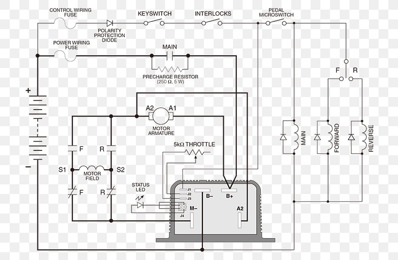
The armature (or rotor) is an you flip the magnetic field just by changing the direction of the electrons flowing in the wire (you do that by. 4 wire reversible psc motor. Electric motor wiring diagram video. And there are many other. As is known, current is the orderly movement of charged particles along conductors of an electric current. Electrical wiring electrical wiring systems wiring. Classification of electric motors, their advantages, and disadvantages. I have compiled a group of single phase electric motor wiring diagrams and terminal connections below. It shows how the electrical wires are interconnected and can also show where fixtures and components may be connected to the system. Electric motor wiring 4.complete electrical motor wiring diagram 5. At the bottom of this post is also a video about dc shunt … For specific leeson motor connections go to their website and input the leeson catalog # in the review box, you will find connection data, dimensions, name plate data, etc. How to calculate your electricity bill.